

Preface
The
following document has been produced to give relatively concise
information on lowering a type 2 VW. Safety precautions in the lifting
of vehicles or removal of components are not to be discussed, as it is
felt common sense prevails.
Introduction
The VW Type 2 suspension is torsional based,
torsion can be thought of as the angular stiffness of metal along its
axis. What this means is that suspension is derived from the 'springy'
properties of metal. The rear suspension comprises of two torsional
bars. The bar ends are machined with little 'v' grooves (splines) used for location and connectivity. The inner bar ends are locked in position and the outer ends attach to metal plates (spring-plates)
that connect the rear hub-carriers. This set-up allows the outer hub
assemblies radial movement to be controlled by the rotational twist of
the torsion bar.
The front suspension has two sets of torsion leaves.
The leaves comprise of a stack of long thin metal strips and are housed
inside each horizontal tube of the front beam. Which are locked into
place via a centralised internal block, which has internal machining to
match the exact cross-sectional area of the set of leaves. A grub-screw
and lock-nut locate the leaves into the central block and hold them
inplace. A trailing arm is attached to each end of the torsion leaves.
The arms have radial movement due to the torsional characteristics of
the leaves. Bolted in between the two trailing arms on each side of the
beam is a stub-axle this carries either the drum or disc, depending on
year of vehicle.
The rear of the vehicle is lowered without any
special equipment or modifications. It is a simple matter of removal
and reassembly. The principle of lowering the rear of the vehicle is to
change the spring-plate's angular relationship to the body's horizontal
line using the splines. The principle of lowering the front suspension
is to change the angular position of the torsion leaves. This is
accomplished by rotating the centralised internal block either by
fitting an adjuster or to cut'n'twist the beam tubes to allow
the re-positioning of the internal block. The latter method, is
undoubtedly the cheapest method, but does not allow for any adjustment.
So care must be taken to satisfactorily calculate the required drop
before any welding is carried out. The instructions presented here are
based on the cut'n'twist method. Fitting of adjusters should be carried
out with manufacturer instructions, but it is envisaged that if
adjusters are to be fitted. Then a pair should be fitted, one on each
beam to maintain torsional balance of the suspension.
Rear Lowering
The
rear suspension on the type 2 is relatively straight forward to modify
no special tools are required. Just what can be usually found in a
competent mechanics tool kit? The procedure is as follows :
1. Remove
rear wheels then remove the bolts holding the hub-carrier to the
spring-plate and then move the carrier out of the way being careful not
to damage the brake pipe in the procedure. The bolts holding the plate
to carrier will be very tight and will necessitate the use of an
appropriate length ‘breaker bar’. Also the lower nut and bolt has very
limited access and it is advisable to remove the handbrake cable to
allow sufficient access for the socket and extension bar.
2. Remove
the pressed metal cover from the front of the spring-plate and then the
outer rubber bush from the torsion bar housing.
3. Place two punch
marks at 12 o'clock orientation. One on the torsion bar end, the other
on the spring-plate. This gives a reference for adjustment and if
errors occur.
4. Carefully remove the spring-plate without
removing the torsion bar from its inner location. If this proves
difficult, wedge the rear of the spring-plate against the cast backing
of the bush housing. Then using a large drift, hammer the torsion bar
inwards to drive it into its inner location. Repeat this method slowly
drifting the spring-plate off the torsion bar.
5. Rotate the spring plate the appropriate number of torsion bar splines. Then reassemble in reverse order.
For
‘fine tuning’ the amount or rear drop a combination of inner and outer
splines can be used. This is discussed a little later in the document.
The amount of drop available at the rear is as follows:
Pre ‘72
Vans
manufactured before 1972 have 48 splines on the outer rear torsion bar.
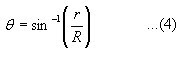
This constitutes 7.50 of rotation per spline. The distance from the
centre of the torsion bar to the centre of the driveshaft is ####. This
is due to the trigonometric relationship given in (1) and illustrated
in figure 5.

Post ‘72
Vans
manufactured after ’72 have 52 splines on the outer rear torsion bar.
This gives approximately 6.90 of rotational movement of drop per spline
using the same relationship as given in (1).
Note
Vehicles
with ‘type 4’ engines fitted originally have longer spring-plates than
their 1600 counterparts, but maintain the same number of outer splines
(52). This effects the amount of drop per spline due to a longer radius.
The
following document has been produced to give relatively concise
information on lowering a type 2 VW. Safety precautions in the lifting
of vehicles or removal of components are not to be discussed, as it is
felt common sense prevails.
Introduction
The VW Type 2 suspension is torsional based,
torsion can be thought of as the angular stiffness of metal along its
axis. What this means is that suspension is derived from the 'springy'
properties of metal. The rear suspension comprises of two torsional
bars. The bar ends are machined with little 'v' grooves (splines) used for location and connectivity. The inner bar ends are locked in position and the outer ends attach to metal plates (spring-plates)
that connect the rear hub-carriers. This set-up allows the outer hub
assemblies radial movement to be controlled by the rotational twist of
the torsion bar.
The front suspension has two sets of torsion leaves.
The leaves comprise of a stack of long thin metal strips and are housed
inside each horizontal tube of the front beam. Which are locked into
place via a centralised internal block, which has internal machining to
match the exact cross-sectional area of the set of leaves. A grub-screw
and lock-nut locate the leaves into the central block and hold them
inplace. A trailing arm is attached to each end of the torsion leaves.
The arms have radial movement due to the torsional characteristics of
the leaves. Bolted in between the two trailing arms on each side of the
beam is a stub-axle this carries either the drum or disc, depending on
year of vehicle.
The rear of the vehicle is lowered without any
special equipment or modifications. It is a simple matter of removal
and reassembly. The principle of lowering the rear of the vehicle is to
change the spring-plate's angular relationship to the body's horizontal
line using the splines. The principle of lowering the front suspension
is to change the angular position of the torsion leaves. This is
accomplished by rotating the centralised internal block either by
fitting an adjuster or to cut'n'twist the beam tubes to allow
the re-positioning of the internal block. The latter method, is
undoubtedly the cheapest method, but does not allow for any adjustment.
So care must be taken to satisfactorily calculate the required drop
before any welding is carried out. The instructions presented here are
based on the cut'n'twist method. Fitting of adjusters should be carried
out with manufacturer instructions, but it is envisaged that if
adjusters are to be fitted. Then a pair should be fitted, one on each
beam to maintain torsional balance of the suspension.
Rear Lowering
The
rear suspension on the type 2 is relatively straight forward to modify
no special tools are required. Just what can be usually found in a
competent mechanics tool kit? The procedure is as follows :
1. Remove
rear wheels then remove the bolts holding the hub-carrier to the
spring-plate and then move the carrier out of the way being careful not
to damage the brake pipe in the procedure. The bolts holding the plate
to carrier will be very tight and will necessitate the use of an
appropriate length ‘breaker bar’. Also the lower nut and bolt has very
limited access and it is advisable to remove the handbrake cable to
allow sufficient access for the socket and extension bar.
2. Remove
the pressed metal cover from the front of the spring-plate and then the
outer rubber bush from the torsion bar housing.
3. Place two punch
marks at 12 o'clock orientation. One on the torsion bar end, the other
on the spring-plate. This gives a reference for adjustment and if
errors occur.
4. Carefully remove the spring-plate without
removing the torsion bar from its inner location. If this proves
difficult, wedge the rear of the spring-plate against the cast backing
of the bush housing. Then using a large drift, hammer the torsion bar
inwards to drive it into its inner location. Repeat this method slowly
drifting the spring-plate off the torsion bar.
5. Rotate the spring plate the appropriate number of torsion bar splines. Then reassemble in reverse order.
For
‘fine tuning’ the amount or rear drop a combination of inner and outer
splines can be used. This is discussed a little later in the document.
The amount of drop available at the rear is as follows:
Pre ‘72
Vans
manufactured before 1972 have 48 splines on the outer rear torsion bar.
This constitutes 7.50 of rotation per spline. The distance from the
centre of the torsion bar to the centre of the driveshaft is ####. This
is due to the trigonometric relationship given in (1) and illustrated
in figure 5.
Post ‘72
Vans
manufactured after ’72 have 52 splines on the outer rear torsion bar.
This gives approximately 6.90 of rotational movement of drop per spline
using the same relationship as given in (1).
Note
Vehicles
with ‘type 4’ engines fitted originally have longer spring-plates than
their 1600 counterparts, but maintain the same number of outer splines
(52). This effects the amount of drop per spline due to a longer radius.